CHALLENGE

Multi-stage manufacturing can introduce uncertainty and process deviation, which accumulate into end part results that are not accurate. Corrective investigations are challenging to perform without a systematic approach and the proper tools.

SOLUTION

  • Artec 3D Space Spider scanner
  • Geomagic® Control X™ metrology and quality management software by 3D Systems
  • Geomagic® Design X™ reverse engineering software by 3D Systems
  • 3D Sprint® build client software by 3D Systems
  • ProJet® MJP 2500 IC 3D printer by 3D Systems

RESULTS

  • Exceeded foundry expectations and improved results with minimum iterations (one) by refining the additively-manufactured, tool-less pattern process with 3d scanning and inspection nets.
  • Reduced finishing costs by 27% by reducing secondary machining operations.
  • Increased total end part accuracy by 14%.

As new production technologies evolve, new technical challenges arise in manufacturing the best possible part. Often a contract manufacturer has to tune the new process significantly the first time it attempts production to understand elements such as shrinkage, surface finish, and repeatability. Additive manufacturing (AM) is no exception, and yet tools to track these elements for this production methodology have lagged behind. That is now changing.

Most manufactured goods follow a common process through their life cycle to production. Design, manufacture, inspect is a generalized way to consider process, stages, and responsibilities, each one being key to producing high-quality parts. Depending on the complexity and nature of the part being manufactured, the real workflow can have many tuning loops and feedback.

Manufacturing workflow

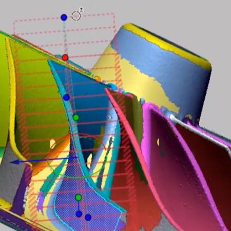
The following workflow example demonstrates how the Artec 3D Space Spider scanner and Geomagic Control X software together provided total shape capture and analysis on 3D-printed wax casting patterns and cast parts at all stages in the design, prove out, and manufacturing process.

Design, pattern making, casting, and quality control workflow infographic for Geomagic Control X inspection software and Artec 3D Space Spider scanner
  • Artec Studio scanning software

    Artec Studio scanning software

  • The Artec 3D Space Spider is an ultra-high-resolution handheld 3D scanner that excels at precisely capturing small objects and complex details for dimensional inspection.

    With plug-and-play operation, the Space Spider scans objects easily, without complicated preparation and extensive user training, allowing customers to digitize parts anywhere. The Artec 3D proprietary target-free algorithms allow the scanner to track the object by its shape and color alone—no need to apply targets to the object.

Geomagic Control X from 3D Systems is an industrial metrology software that enables root cause analysis (RCA) and correction for manufacturing. As a 3D scan-native software, Geomagic Control X is an ideal solution for metrology with portable measurement devices. With Geomagic Control X, more people in your organization can measure faster, more often, and more completely—from anywhere.

The total solution provides unique insight into successful production in a complex manufacturing process. The result? Greatly-improved overall final part quality, accuracy, and repeatability.
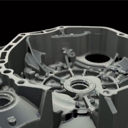
Part being scanned

Design

For this workflow example, we replicated a real customer project, but generalized the details. In this case, the customer was developing a specialized, autonomous-driving, light-duty vehicle. To speed time-to-market, they selected and combined a range of components and systems from vehicles on the market today to complete a working prototype. In this process, they found a specific steering knuckle (one each per) was valuable to the project and they needed to digitize and capture the design so that they could further modify and manufacture it in a light-weight material.

To begin work, they 3D scanned and reverse engineered the original casting. They used the Artec 3D Space Spider scanner for rapid digitization and then quickly and accurately modeled the part in Geomagic Design X with a unique hybrid-modeling approach. Typically, customers will follow either an as-built (very accurate) or design-intent (dimension-driven) modeling method. A hybrid modeling approach consists of combining both of those concepts to deliver a CAD solid model result that has both dimensioned features as well as highly-accurate NURBs surfaces. Using this strategy, they completed the model in under 1.5 hours and live-transfered to SOLIDWORKS as feature-based CAD.

  • Original part scan

    Original part scan

  • Hybrid CAD model

    Hybrid CAD model

  • Defeatured model for print

    Defeatured model for print

  • Unfinished wax print from the ProJet® MJP 2500 IC 3D printer by 3D Systems

    Unfinished wax print from the ProJet MJP 2500 IC

    Sample cross section of sparse infill mode printed on the ProJet® MJP 2500 IC 3D printer by 3D Systems

    Sample cross section of sparse infill mode printed on ProJet MJP 2500 IC

  • Pattern Making

    AM has been used in aerospace and automotive applications to produce sacrificial casting patterns for decades. With recent advances in 3D printing, industrial-grade patterns can be printed in wax or polymer at a significantly lower cost, which work seamlessly in the investment-casting process. 3D Systems is seeing more distributed adoption of tool-less additive pattern making and will continue to grow as the technology becomes more accessible, rapid, and precise.

    For any additive process that involves heat energy in material deposition or post processing, there is some amount of part warpage and settling that could occur. Parts that have significant mass or a significant cross-sectional area will retain heat for longer than smaller or thinner parts.

    Based on this knowledge, 3D Systems tested two printing methods with the goal of having the lowest possible cost of printed goods and the highest level of dimensional stability: a completely solid wax-printing method as well as a thin, shell/sparse wax-infill method. Both were prepared with 3D Sprint build client software and printed on the ProJet MJP 2500 IC 3D printer that produces wax casting patterns. From prior experience, we found that a 2 mm shell with a 50% sparse infill ratio produces high-quality, stable parts when printing relatively large parts.

    After post processing and cooling time, we used the same Artec 3D Space Spider scanner to scan the two patterns with relative ease. The unique shape of the parts, the green wax color, and the slight dulling and whitening effect of the post process enabled our scanning technician to capture the models smoothly using Geometry + Texture tracking.

  • Using Geomagic Control X, we imported the 3D Sprint build file directly and inspected each part in its exact print orientation for the inspection routine. Knowing that we would be scanning the subject part iteratively to improve the process, we were able to set up one detailed inspection project and duplicate it several times while maintaining the entire process development history in a single Geomagic Control X file. After completing the scans, we simply dropped each new STL file into the Geomagic Control X project and the evaluation process automatically took over, resulting in high-quality, repeatable reports.

    We found that, generally, all areas with machining offsets were within the casting tolerance, but the more free-form areas presented trends outside a tight tolerance band. We believe this properly correlated our assumptions that large cross-section areas retain heat and potentially change shape when cooling.

    Our comprehensive analysis for this stage helped us draw some conclusions that 3D printing with the wax pattern was not only more cost-effective, but also more dimensionally-compliant after post processing.

    • Material usage was reduce by about 35%.
    • Material cost was reduced by about 27%.
    • Overall compliance with tolerances were increased by about 10% (using 3D comparison).
    • The solid part did not pass the tolerance threshold
    • The infill part passed the tolerance threshold.
    • Long-term dimensional stability at room temperature was improved over the solid part.
  • Solid wax pattern analysis

    Solid wax pattern analysis

    Wax pattern with infill analysis

    Wax pattern with infill analysis

Casting

Investment casting is a trusted manufacturing methodology that dates back 5,000 years and has been established in global industrial manufacturing since the dawn of the industrial revolution a few hundred years ago.

The casting process is now quite mature, repeatable, well-known, and covered by simulation software to help reduce the chance of internal part defects. With an experienced foundry partner and minimal customer effort, it’s possible to deliver additively-manufactured patterns and produce parts that are free of internal defects and generally exceed commonly-held process tolerance expectations for casting.

Customers who actively participate in testing the result and process iteration can expect to achieve significantly higher-quality output when tuning their part geometry because of the stability of the casting process itself.

  • Shrinkage or contraction allowance
  • Shrinkage is a known result of the casting process. Typically, a foundry provides customers some guidance to compensate for the known shrinkage for a specific material for a part size defined by the bounding box. Because of the geometric complexity and compounded by the physical casting process, it is common to see non-uniform shrinkage with most parts. As a result, casting can be regarded generally as a loose-tolerance process.

    During the casting processes for the steering knuckle, we investigated a shrinkage rate that would be suitable for the model and material. After consulting with the casting facility, a 2% uniform scale was recommended to produce an accurate part. To investigate the effect that 3D scanning and a precision scale factor can have on end-part accuracy, we produced a wax pattern with a 2% scale factor as advised and supplied it to the foundry.

  • Quality Control

    3D Systems further inspected the returned castings to verify whether the uniform scaling factor conformed to expected tolerances. Following the generalized foundry specification, it provided a part that was definitely inside the partner’s stated achievable accuracy for a part of roughly the same size. However, closer inspection with the Cross Section compare tool in Geomagic Control X indicated some obvious areas where better application of the precision scale factor could improve the overall accuracy of the finished part meaningfully.

    This cross-section silhouette comparison with a tight-tolerance band clearly shows outer borders with blue coloring and inner borders with orange and red coloring. The outer profile confirms an under-size condition where the actual part boundary is inside the reference boundary. The inner profile shows that the center cylinder feature is dimensionally smaller than intended, but appears as outside of the reference feature. This indicates that the total silhouette shadow of the part has a scale difference that can be corrected by increasing the scale factor, printing, and casting again.

    Previous casting process improvement investigations have provided some insight on relative adjustments from recommended standard values that we can apply. We printed a second wax pattern with a non-uniform scale factor of 2.2%, 2.3%, and 2.7% in X, Y, and Z respectively and supplied it to the foundry.

    With a final inspection on the precision compensated pattern, we were able to draw some conclusions about the pattern-to-part process:

    • The precision scaled pattern provided results that exceeded foundry expectations.
    • Overall dimensional compliance of the scale-corrected part increased by about 14%.
    • At least one major machining operation could be avoided with the increase in precision.
    • Total overall part production cost was reduced.
    • We need future analysis to see if further precision can be applied to reduce machine operations in general.
  • Cross section of scale error analysis

    Cross section of scale error analysis

    Final cast part

    Final cast part

    Final casting analysis

    Final casting analysis

Conclusion

Efficiency is key to maintain profit and reduce waste in human and manufacturing cycles. With the Artec 3D Space Spider scanner and Geomagic Control X, we were able to improve the total overall quality of the manufactured part by analyzing each stage of the process with the minimum possible tuning cycles and iteration. Reducing iteration and guesswork, saving time and money, and faster time to market are key benefits of using a total solution for high-quality 3D scanning and scan-native industrial inspection software.